 |

LabeLase� Producer
|
|
LabeLase� Producer
|
|
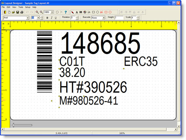
Layout Designer Form The Layout Designer form is a WYSIWYG editor for creating and editing tag layout files. The form provides tools for creating text, barcodes, graphics, lines, boxes, ellipses, vector lines, vector rectangles and vector ellipses. Tools for field alignment, editing, formatting, etc. are also provided. The form appears as shown in the example below. New in Version 1.30 is the New Layout feature, with the "wizard" feature.
|
||||||||||||||||||||
|
||||||||||||||||||||
| Note that at the top of the form, in the title bar, is the name
of the currently loaded tag layout file.
The middle part of the form presents a graphical image of the tag, including all of the fields that have been added to it. Rulers along the left side and top show the tag width and length respectively in the current units of measure. The image can be scrolled up/down and left/right as needed to see the entire tag. You may also zoom in/out as needed to see the entire image at once.
|
||||||||||||||||||||
| Menu
|
||||||||||||||||||||
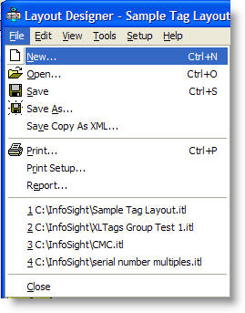
| File Menu
New - Creates a new layout with a blank tag. If you have changed the current layout without saving your changes, the program will prompt you to save first. New to Version 1.30, you may choose to create a blank layout, load a layout template, or use the "wizard" to create the layout. Open - Allows you to open a tag layout saved on your PC's hard disk drive, a floppy drive, or a network shared folder. Save - Saves the current layout to disk. The file is saved using its current name, in the folder from which it was loaded. If the file does not have a name, a Save dialog will prompt you to enter a name and destination folder. Save As - Allows you to save the layout with a different name and/or a different destination folder. Save Copy As XML - Allows you to save the layout in XML file format. This format is useful if you plan to download an entire layout to Producer using the XML download protocol. Saving your designed layout in XML format will aid you in creating your download file. Print - Prints a representation of the tag layout to a printer connected to your PC or to your local network. Print Setup - Allows you to specify the printer to use for printing tag layout reports. Report - Allows you to view and print a report of the currently loaded layout. A new window will appear showing the report for the layout. You will have the option of printing the report, or saving it to a file. Exit - Exits the tag layout designer form, returning to the main form. Between the Print Setup menu choice and the Exit choice is a list of up to 4 tag layout filenames. The program keeps track of the last four layouts loaded by the supervisor and allows them to be re-loaded quickly by clicking on the filename.
|
||||||||||||||||||||
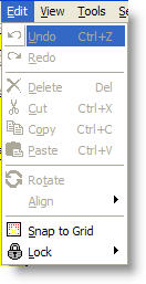
| Edit Menu
Undo - This menu item is available after you have made a change to the layout, such as moving, rotating or resizing a field. When you select Undo, your last change will be rolled back by one step. If you made a change to multiple selected fields, each field's change will be undone separately. There is no limit to the number of operations that can be undone. Redo - This menu item allows you to redo changes that you previously have undone. If you have not undone any changes, then there will be nothing to redo as shown in this example. Delete - Delete the selected fields. If no fields are selected, this menu item will not be accessible. Any field that is deleted can be restored using the Undo feature. Cut - Delete the selected field and place it on the program's "clipboard". If more than one field is selected, then each is placed on the clipboard. If no fields are selected, this menu item will not be accessible. Any field that is cut can be restored using the Undo feature. Copy - Copy the selected field to the program's clipboard. If more than one field is selected, then each one is copied to the clipboard. If no fields are selected, this menu item will not be accessible. Copying fields does not affect the layout. Paste - Paste the fields in the clipboard to the layout. Multiple fields are pasted as a group. If no items are in the clipboard, then this menu item is not accessible. Rotate - Rotate the selected field or fields by 90 degrees in the clockwise direction. If more than one field is selected, they will be rotated as a group. Any fields that are rotated can be restored using the Undo feature. Align - Provides a list of alignment tools. Alignment tools are only accessible if more than one field is selected.
Left - Align all fields to the leftmost edge. Right - Align all fields to the rightmost edge. Top - Align all fields to the topmost edge. Bottom - Align all fields to the bottommost edge. Middle - Align all fields to the vertical middle of the fields. Fields will be centered along an imaginary horizontal line. Center - Align all fields to the horizontal middle of the fields. Fields will be centered along an imaginary vertical line. Note that the terms top, bottom, left and right refer to the fields themselves, not the display screen.
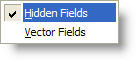
Snap To Grid - Enables or disable the "snap to grid" feature. When enabled, all fields that are added or moved will have their coordinates adjusted to match the current grid setting. This is an aid in lining up fields. If this feature is enabled when one or more fields are selected, the selected fields will be snapped to the grid. Lock - The lock menu allows you to lock certain types of fields so they cannot be selected, edited, etc.
Lock - Hidden Fields - New in V1.63 - Locks fields that are marked as "hidden" so that they cannot be selected, moved or edited. This is useful when hidden fields are used to indicate "background" features, especially with the LabeLase 1000P plate printer, and you want to manipulate the printed fields without the background fields interfering. Lock - Vector Fields - New in V1.80 - Locks vector fields so that they cannot be selected, moved or edited. This is useful when vector fields are used to surround and encompass other fields and you want to manipulate the printed fields without the vector fields interfering.
|
||||||||||||||||||||
| View Menu
Zoom Out - Reduces the size of the tag image display so that more of the layout can be seen on the screen. Zoom factors range from 10% to 200%. Note that as you zoom out, detail is lost when the image is reduced in size. Zoom In - Increase the size of the tag image display. This allows you to see more detail, at the expense of seeing less of the tag image at one time. Anchors - Each field is anchored to the layout in the lower left corner of the field. It is sometimes handy to see this anchor point. When anchors are enabled, a small red circle is drawn on the display at each field's anchor point. Grid - A grid display can be overlaid onto the tag layout image to aid in locating fields. The grid is shown as a matrix of green dots on the tag background. The size (density) of the grid is controlled in the Preferences dialog. When the "Snap to Grid" feature is enabled, this is the grid that controls the field location. Normal - Set the view mode to "normal". The tag is shown such that the direction of tag feed is from right to left. Portrait - Set the view mode to "portrait". The tag view is rotated such that the direction of tag feed is from bottom to top. This view makes it easier to layout tags whose text is rotated 90 degrees from normal. Toolbars - The designer form has several toolbars that make it easy to access certain program features. If your display is small or appears cluttered, you can turn off the view of these toolbars as needed with the Toolbars submenu.
Generate Image - Select this menu item to force the tag image to be redrawn.
|
||||||||||||||||||||
| Tools Menu
Pointer - This tool is used to deselect the current tool. Text - Used to add a text field to the layout. Barcode - Used to add a barcode to the layout. Graphic - Used to add a graphic image (bitmap) to the layout. Line - Used to add a line to the layout. Box - Used to add a box outline to the layout. Ellipse - Used to add an ellipse (or circle) to the layout. Vector Line - Used to add a vector line to the layout. New in V1.80, vector lines are used to cut a linear shape into special tag materials. Vector Rectangle - Used to add a vector rectangle to the layout. New in V1.80, vector rectangles are used to cut a rectangular shape into special tag materials. Vector Ellipse - Used to add a vector ellipse to the layout. New in V1.80, vector ellipses are used to cut a elliptical or circular shapes into special tag materials. Vector Polygon - Used to add a vector polygon to the layout. New in V1.90, vector polygons are used to cut a irregular shapes into special tag materials.
Once a tool is selected, you can add a field by clicking on a blank space in the tag layout where you wish the field to reside. When a field is added, its associated field editor will automatically appear allowing you to specify the details of the field.
|
||||||||||||||||||||
| Setup Menu
Geometry - This menu item will open the Geometry form, which allows you to configure the physical characteristics of the tag, including length, width, holes, slots, bare edges, etc. Units of Measure - This menu item will activate the Units form that allows you to specify either English or Metric units of measure. When in English units, the basic unit of measurement is the inch. While in Metric units, the basic unit of measurement is millimeters. Serial Numbers - This menu item will activate the Serial Numbers form, which allows you to configure the auto incrementing feature of the layout. Each layout can have two groups of two each numeric serial number fields. Each field has the ability to increment up or down between a set range of numbers. When the first number in each group reaches its limit, it rolls over to the opposing limit and causes the second number in the group to increment (or decrement as needed.) If you want to implement alphanumeric sequencing, this must be done in the individual text field editor. User Tables - This menu item will activate the User Defined Tables form, which allows you to configure certain features related to date codes and shift codes. These codes can then be placed into text fields using the special % flags feature. Operator Data Entry - This menu item will activate the Operator Data Entry Configuration form, which allows you to configure how the operator will interact with the layout during the printing process. It allows you to add fields that the operator must enter prior to printing, configure whether the operator has access to the quantity and serial number fields, etc. Preferences - This menu item will activate the Preferences form, which allows you to configure certain program preferences related to layout design.
|
||||||||||||||||||||
| Help Menu
Contents - This menu item will activate the Windows Help for the Producer program, including indexed search, tutorials, etc.
|
||||||||||||||||||||
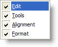
| Tool Bars
Just under the form's menu are the toolbars. These toolbars provide quick access to many of the forms functions.
Four toolbars are available, and each can be individually enabled or disabled for display.
The Edit toolbar provides the following functions from left to right: Exit, New, Open, Save, Print, Undo, Redo, Zoom In, Zoom Out, Set Zoom %, Rotate, Delete, Help
The Tool toolbar provides the following functions from left to right: Pointer, Text, Barcode, Graphic, Line, Box, Ellipse, Vector Line, Vector Rectangle, Vector Ellipse, Vector Polygon
The Align toolbar provides the following functions from left to right: Align Left, Right, Top, Bottom, Middle, Center
The Format toolbar provides the following functions from left to right: Font Name, Font Size, Font Style (bold, italic, underline), Rotation, Barcode Symbology, Barcode Height, Barcode Scale. When you select a field on the layout, its properties will be reflected in the settings of this toolbar. Changing a setting on the toolbar will change the selected field(s). If no fields are selected, the toolbar settings show the current "default" settings as determined in the preferences editor.
|
||||||||||||||||||||
| Status Bar
At the very bottom of the main form is the status bar. Several panels are used to provide information to the operator about the editing process. As shown here, the leftmost panel shows details about the field that the mouse is currently pointing to. The second panel shows the mouse's current position in tag coordinates, relative to the lower left corner of the tag. The third panel is blank and is reserved for future use. The last panel shows the current zoom magnification percentage.
|
||||||||||||||||||||
| Adding a Field
Before you can add a field to your layout, you must first select the appropriate tool. The Text tool is used to add text fields
to the layout, the Barcode tool adds barcode fields, etc.
You may select the desired tool either from the Tool menu, or from the
Tool toolbar. Only one tool can be selected at a time, so
when you select a tool, the previously selected tool is
deselected. To deselect all tools, select the Pointer Once your chosen tool is selected, you place the field on the layout by clicking on the tag image in the location where the field is to be anchored. If you simply click and release the mouse, the field will be located at the specified position, and the initial size of the field will be determined by the settings in the Format toolbar. You may also determine the size of the field by clicking on the desired anchor point and dragging the mouse to form a "stretch box". This box has a dashed green outline and its size determines the size of the field. You can also specify the rotation angle of the field by varying the direction of the stretch box. If you drag up and right of the anchor, the rotation angle will be zero degrees. Drag down and right to specify 270 degrees. Up and left sets the rotation to 90 degrees, and down and left sets 180 degrees. Regardless of the method you use to add the field, when you release the mouse button that field's editor will appear. Each tool has its own editor, which allows you to specify the details about the field's composition. The various field editors are described below.
|
||||||||||||||||||||
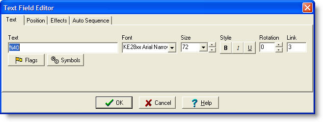
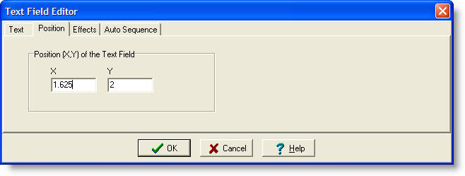
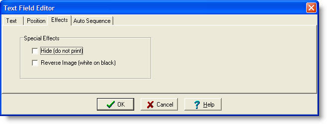
| Text Field Editor
Each text field is defined by several pieces of information that you must supply. This information is entered on multiple tabs, and includes: Text Tab |
||||||||||||||||||||
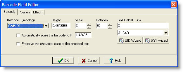
| Barcode Field Editor
Each barcode field is defined by several pieces of information that you must supply. This information is entered on multiple tabs, and includes: Barcode Tab |
| Error Correction Level | Number of Error Correction Codewords |
|---|---|
| 0 | 2 |
| 1 | 4 |
| 2 | 8 |
| 3 | 16 |
| 4 | 32 |
| 5 | 64 |
| 6 | 128 |
| 7 | 256 |
| 8 | 512 |
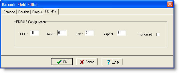
Rows � Enter the desired number of rows in the resulting symbol. This setting is highly dependant on the number of codewords in the symbol, and it is recommended that you leave the field set to its default setting of 0, which will allow the program to determine the appropriate number of rows. If you specify the number of rows, you must enter a number between 3 and 90 inclusive.
Cols � Enter the desired number of columns in the resulting symbol. This setting is highly dependant on the number of codewords in the symbol, and it is recommended that you leave the field set to its default setting of 0, which will allow the program to determine the appropriate number of columns. If you specify the number of columns, you must enter a number between 1 and 30 inclusive.
Aspect � Enter the desired aspect ratio (number of rows to columns) for the symbol. The default value of 3 is recommended. If the Cols field is non-zero, then the Aspect setting is ignored.
Truncated - If this check box is checked, then the symbol will be printed in its truncated form. In a relatively "clean" environment where tag damage is unlikely (e.g. an office), the right row indicators can be omitted, and the stop pattern can be reduced to one module. This truncated form reduces the non-data overhead in the symbol (thus reducing its size) with the trade-off in reduced performance and robustness, or the ability to withstand degradation.
If the printer is configured as a rotational printer (printing around the circumference of a cylinder), and 2D Data Matrix symbology is selected, then additional fields will be enabled to configure the projection of the code onto the object surface.
Enable 2D Projection showing X percent � Check this box and enter the percentage of the apparent diameter / radius of the object that is to contain the 2D code.
Project Asymmetrically � To project the 2D code around the apparent diameter of the cylinder, leave this box unchecked. The code will be �stretched� on both sides to enhance perspective when viewed directly from above. Checking the box will project the 2D code around the apparent radius of the cylinder, thus �stretching� it only on one side. This will allow the reader to read the code from an off-center position that avoids direct reflections from the object�s surface.
Each graphic field is defined by several pieces of information that you must supply. This information includes:
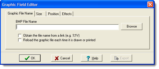
BMP Filename - You must specify the file pathname of the graphic image. A Browse button is provided that will show an Open dialog for searching the file system for the desired BMP file. You may load a file from your PC's hard drive, a floppy disk or a network folder.
New in V1.92
Obtain the file name from a link - Check this box to force producer to obtain the name of the bitmap file from another field (i.e. from a link to an Operator Data Entry field.) Checking this box also checks the Reload box (see below).
Reload the graphic file each time it is drawn or printed - Check this box to have Producer reload the file whenever it is used. When this box is not checked, the bitmap is stored in the layout itself and the name of the file is no longer used. When this box is checked, the graphic file is dynamically loaded when needed.
New in version 1.92
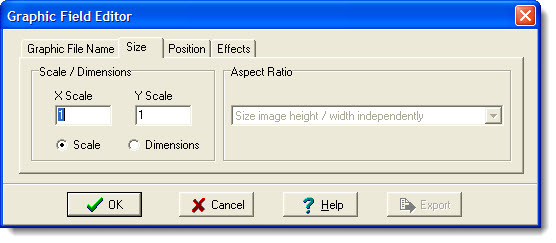
Scale - Select how you want to control the size of the graphic image. Select Scale if you want the image to be sized using a multiplication factor. Enter the scaling factor for both the X and Y axes. The original image will be scaled as specified.
X Scale - The horizontal scaling factor. This number may be less than 1.0 to scale the image down, or greater than 1.0 to scale the image up.
Y Scale - The vertical scaling factor. This number may be less than 1.0 to scale the image down, or greater than 1.0 to scale the image up. Note that if the X and Y scaling factors are different (this is allowed) then the graphic image will be distorted. This may or may not be a desired result.
Dimensions - Select how you want to control the size of the graphic image. Select Dimensions if you want the image to appear as a specific size on the tag. Enter the size in inches (mm) for both the Width and Height. The original image will be scaled as needed, either up or down, to fit the desired dimensions. When scaling using dimensions, you can control the aspect ratio as well.
Aspect Ratio - The aspect ratio can be controlled whenever you are using the "Dimensions" method of sizing.
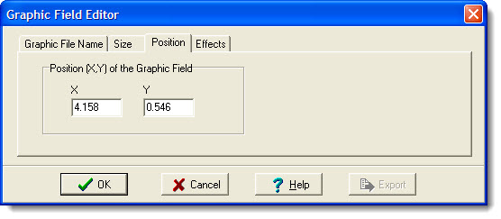
X - The X coordinate of the lower left corner of the graphic is specified here. Note that this value is already filled in for you based on where you clicked the mouse.
Y - The Y coordinate of the lower left corner of the graphic is specified here. Note that this value is already filled in for you based on where you clicked the mouse.
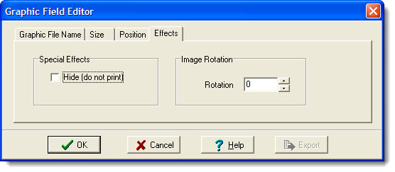
Hide (do not print) - This checkbox will cause the graphic to be hidden (not printed.) Note that hidden fields are shown in yellow in the designer, but are not printed on the tag. NOTE: If you intend to place other fields on top of the hidden field, be sure to create the hidden field first, before adding the other fields.
Rotation - The Rotation value specifies the number of degrees to rotate the graphic image. Enter 0, 90, 180 or 270 or use the up/down control to change the field. Note that the rotation of the field is relative to the X/Y coordinate of the lower left of the graphic.
An Export button is provided to allow you to save the bitmap to a file. You will be asked to specify a filename for the destination bitmap.
Each line field is defined by several pieces of information that you must supply. This information includes:
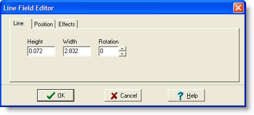
Height - Defines the vertical thickness of the line (Y dimension).
Width - Defines the horizontal dimension of the line (X dimension).
Rotation - Specifies the number of degrees to rotate the line. Enter 0, 90, 180 or 270 or use the up/down control to change the field. Note that the rotation of the field is relative to the X/Y coordinate of the lower left of the line.
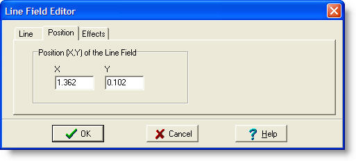
X - The X coordinate of the lower left corner of the line is specified here. Note that this value is already filled in for you based on where you clicked the mouse.
Y - The Y coordinate of the lower left corner of the line is specified here. Note that this value is already filled in for you based on where you clicked the mouse.
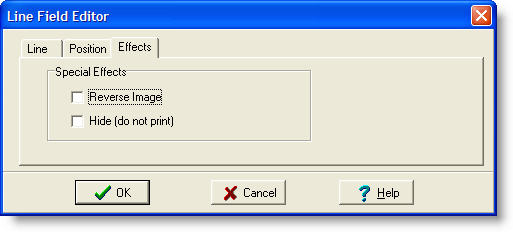
Reverse Image - This checkbox specifies that any other field enclosed by this line should be �reversed� (black into white, white into black.)
Hide (do not print) - This checkbox will cause the line to be hidden (not printed.) Note that hidden fields are shown in yellow in the designer, but are not printed on the tag. NOTE: If you intend to place other fields on top of the hidden field, be sure to create the hidden field first, before adding the other fields.
Each box field is defined by several pieces of information that you must supply. This information includes:
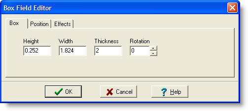
Height - Defines the vertical dimension of the box (Y dimension).
Width - Defines the horizontal dimension of the box (X dimension).
Thickness - Defines the width of the box outline.
Rotation - Specifies the number of degrees to rotate the box. Enter 0, 90, 180 or 270 or use the up/down control to change the field. Note that the rotation of the field is relative to the X/Y coordinate of the lower left of the box.

X - The X coordinate of the lower left corner of the box is specified here. Note that this value is already filled in for you based on where you clicked the mouse.
Y - The Y coordinate of the lower left corner of the box is specified here. Note that this value is already filled in for you based on where you clicked the mouse.
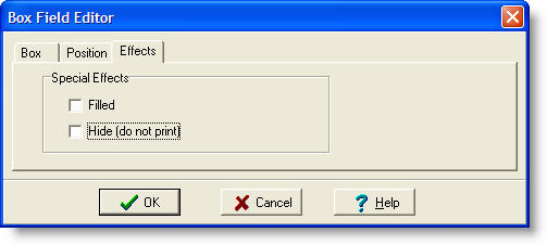
Filled - This checkbox will cause the box to be filled in as a solid figure, rather than just printing the outline.
Hide (do not print) - This checkbox will cause the box to be hidden (not printed.) Note that hidden fields are shown in yellow in the designer, but are not printed on the tag. NOTE: If you intend to place other fields on top of the hidden field, be sure to create the hidden field first, before adding the other fields.
Each ellipse field is defined by several pieces of information that you must supply. This information includes:
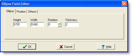
Height - Defines the vertical dimension of the enclosing rectangle (Y dimension).
Width - Defines the horizontal dimension of the enclosing rectangle (X dimension).
Rotation - Specifies the number of degrees to rotate the ellipse. Enter 0, 90, 180 or 270 or use the up/down control to change the field. Note that the rotation of the field is relative to the X/Y coordinate of the lower left of the enclosing rectangle.
Thickness - Defines the thickness of the ellipse outline.
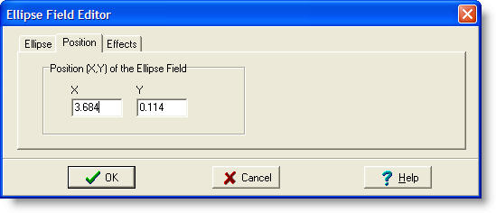
X - The X coordinate of the lower left corner of the enclosing rectangle is specified here. Note that this value is already filled in for you based on where you clicked the mouse.
Y - The Y coordinate of the lower left corner of the enclosing rectangle is specified here. Note that this value is already filled in for you based on where you clicked the mouse.
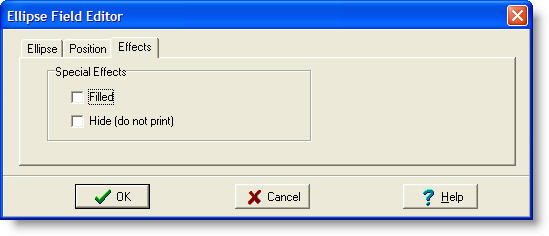
Filled - This checkbox will cause the ellipse to be filled in as a solid figure, rather than just printing the outline.
Hide (do not print) - This checkbox will cause the ellipse to be hidden (not printed.) Note that hidden fields are shown in yellow in the designer, but are not printed on the tag. NOTE: If you intend to place other fields on top of the hidden field, be sure to create the hidden field first, before adding the other fields.
Note that if you set the Height and Width fields to the same value, the result will be a perfect circle.
Each vector line field is defined by several pieces of information that you must supply. This information includes:
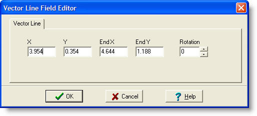
X - The X coordinate of the lower left corner of the line is specified here. Note that this value is already filled in for you based on where you clicked the mouse.
Y - The Y coordinate of the lower left corner of the line is specified here. Note that this value is already filled in for you based on where you clicked the mouse.
End X - Defines the ending X coordinate of the vector line.
End Y - Defines the ending Y coordinate of the vector line.
Rotation - Specifies the number of degrees to rotate the vector line. Enter 0, 90, 180 or 270 or use the up/down control to change the field. Note that the rotation of the field is relative to the X/Y coordinate of the lower left of the line.
Each vector rectangle field is defined by several pieces of information that you must supply. This information includes:

X - The X coordinate of the lower left corner of the box is specified here. Note that this value is already filled in for you based on where you clicked the mouse.
Y - The Y coordinate of the lower left corner of the box is specified here. Note that this value is already filled in for you based on where you clicked the mouse.
Height - Defines the vertical dimension of the box (Y dimension).
Width - Defines the horizontal dimension of the box (X dimension).
Thickness - Defines the width of the box outline.
Rotation - Specifies the number of degrees to rotate the box. Enter 0, 90, 180 or 270 or use the up/down control to change the field. Note that the rotation of the field is relative to the X/Y coordinate of the lower left of the box.
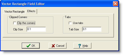
Clip the corners - This checkbox will cause the corners of the rectangle to be clipped (at a 45 degree angle.)
Clip Size - Enter the size of the clip region.
Use Tabs - This checkbox will cause the rectangle to be drawn with tabs (sections that are not burned/cut) at the mid-point of each side.
Tab Size - Enter the size of each tab.
Each vector ellipse field is defined by several pieces of information that you must supply. This information includes:
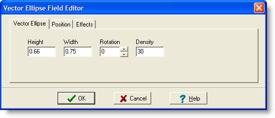
Height - Defines the vertical dimension of the enclosing rectangle (Y dimension).
Width - Defines the horizontal dimension of the enclosing rectangle (X dimension).
Rotation - Specifies the number of degrees to rotate the ellipse. Enter 0, 90, 180 or 270 or use the up/down control to change the field. Note that the rotation of the field is relative to the X/Y coordinate of the lower left of the enclosing rectangle.
Density - Defines the density of the line segments used to draw the ellipse. Enter the value in segments per inch or segments per centimeter depending on the current units of measure.
Note that if you set the Height and Width fields to the same value, the result will be a perfect circle.
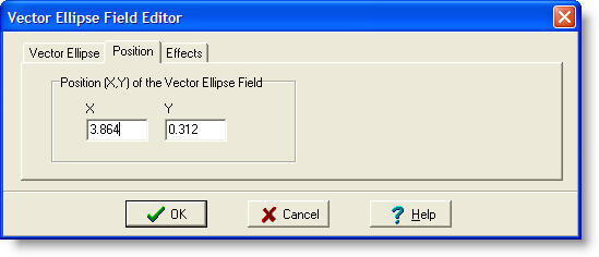
X - The X coordinate of the lower left corner of the enclosing rectangle is specified here. Note that this value is already filled in for you based on where you clicked the mouse.
Y - The Y coordinate of the lower left corner of the enclosing rectangle is specified here. Note that this value is already filled in for you based on where you clicked the mouse.
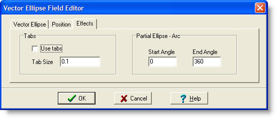
Use Tabs - This checkbox will cause the rectangle to be drawn with tabs (sections that are not burned/cut) at the mid-point of each side.
Tab Size - Enter the size of each tab.
Start Angle / End Angle - Enter the starting and ending angle of the vector ellipse. If you enter 0 and 360, you will get a fully formed ellipse or circle. If you enter less than a full 360 degrees, you will end up with a partial ellipse or arc.
After selecting the vector polygon tool, you must define the line segments that make up the polygon shape. Begin by clicking the mouse at the first vertex (corner) of the first line segment. The polygon tool will remain active as you continue to click at the end of each line segment. To terminate the polygon tool, double click the mouse at the end of the final line segment. After terminating the polygon tool, the Vector Polygon Field editor will appear as shown below:
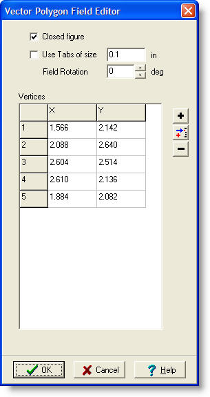 |
Closed Figure - Check this box to have the polygon automatically add one final line segment between the last defined vertex and the first. This will close the shape. Use Tabs - Check this box and enter a Tab Size if you want the polygon to be drawn with tabs (sections of each line segment that are not burned/cut) at the mid-point of each line segment. Field Rotation - Enter the number of degrees to rotate the entire polygon shape. Vertices - This is a list of coordinates for each vertex (point) making up the polygon. You can edit this list as needed to fine-tune the shape. Add, Insert and Delete - These buttons are provided to further refine the list of vertices. |
Fields are selected for special operations using the mouse. Before attempting to select a field, it is a good
idea to deselect all tools by clicking on the Pointer ![]() .
This will make sure that as you select fields you do not inadvertently
add unwanted fields to your layout.
.
This will make sure that as you select fields you do not inadvertently
add unwanted fields to your layout.
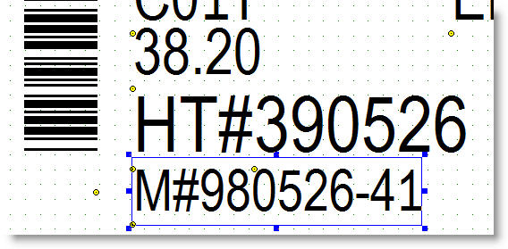
A field may be selected by clicking anywhere within its borders. You may also select a field by dragging a "stretch box" around the anchor point of the field. Note that when no tools are enabled, the color of the stretch box turns from green to red. Below is an example of a single field selection. The selection is indicated by a blue outline around the entire perimeter of the field. In each corner of the selection box, as well as in the middle of each side, are sizer boxes. These sizers allow you to change the size of the selected field by dragging the box with the mouse.
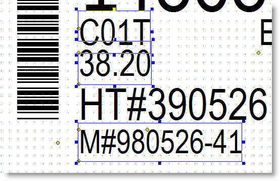
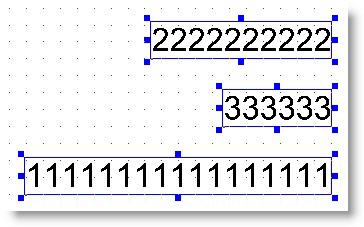
You may select more than one field by holding down the control key while you click on the field. You may also select multiple fields simultaneously by dragging a "stretch box" to encompass the anchor points of all of the desired fields. Below is an example of a multiple field selection.
When multiple fields are selected, dragging a sizer box for any one field will cause all selected fields to be resized accordingly.
Any field can be resized by using the field editor (double click on the selected field) and changing its size or its height and width values.
Selected fields can also be resized by dragging one of its sizer boxes. Dragging one of the top sizer boxes will increase the field's height. Dragging the bottom sizer boxes will increase its height as well as change its anchor point. Dragging a corner box changes both its height and width.
Note that dragging a sizer box for Text and Barcode fields will only change its size/height since the width of these fields depends on other factors such as text content and barcode symbology/content.
Any field can be rotated by using the field editor (double click the selected field) and changing its rotation value setting.
Selected fields can also be rotated by clicking on the Rotate button or selecting the Rotate menu item. If more than one field is selected, the fields will be rotated as a group. Be sure that all of the selected fields have the same initial rotation setting to avoid unexpected results.
If more than one field is selected, they can all be aligned along their top, bottom, left or right edges, or along their horizontal or vertical centerlines using the alignment toolbar or menus.
![]()
Left - Align all fields to the leftmost edge.
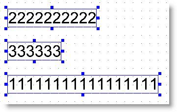
Right - Align all fields to the rightmost edge.
Top - Align all fields to the topmost edge.

Bottom - Align all fields to the bottommost edge.
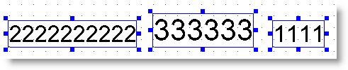
Middle - Align all fields to the vertical middle of the fields. Fields will be centered along an imaginary horizontal line.
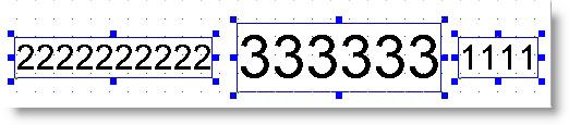
Center - Align all fields to the horizontal middle of the fields. Fields will be centered along an imaginary vertical line.
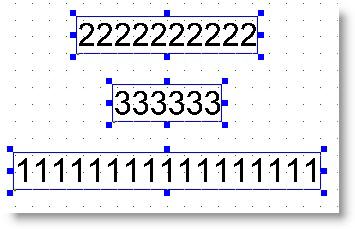
Note that all of the selected fields should have the same rotation angle to avoid unexpected results.
Whenever there are one or more selected fields, you can perform these editing operations on them. Each operation acts on all selected fields as a group.
Cut - Delete the selected field and place it on the program's "clipboard". If more than one field is selected, then each is placed on the clipboard. Any field that is cut can be restored using the Undo feature.
Copy - Copy the selected field to the program's clipboard. If more than one field is selected, then each one is copied to the clipboard. Copying fields does not affect the layout.
Paste - Paste the fields in the program's clipboard to the layout. Multiple fields are pasted as a group. Note that all fields being pasted as a group should have the same rotation angle to avoid unexpected results.
Delete - Delete the selected fields. Any field that is deleted can be restored using the Undo feature.
Note that the program's "clipboard" is not the same as the Windows Clipboard.
Version 1.30 introduced three choices for creating new layout files. The New Layout dialog shown below presents these choices to you.
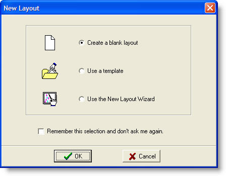
This dialog presents three choices for creating a new layout.
Create a blank layout - This choice simply creates a new, blank, layout using the default dimensions. You may then manually add fields as needed using the various tools.
Use a template - This choice will query you to open a layout file that has been provided as a template. Once you select a template, you may modify it as needed for your application and save it with any filename you choose.
Use the New Layout Wizard - This choice opens the wizard which will guide you through the process of creating the tag layout.
The "wizard" is a dialog that guides you through the process of creating a new layout. Each page of the wizard asks you to provide a few pieces of information about the layout you wish to create. As you supply the information, an image of your layout is shown to you. Below is a description of each phase of the wizard creation process.
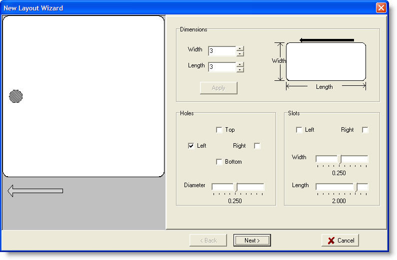
This first page of the wizard allows you to specify the tag geometry. You can change the tag width and length as needed for your application. The width and length are defined as shown in the accompanying diagram. Note that the direction the tag feeds from the printer is right to left in this diagram. After changing the width of length value, click the Apply button to see the new dimensions reflected in the layout image to the left.
This page also allows you to add holes or slots to your layout. Holes can be added at the left or top, and at the right or bottom of the tag. Note that left/top and right/bottom are mutually exclusive. You cannot have left and top holes, nor right and bottom holes. Use the Diameter slider to change the size of the holes. All holes must be the same size.
Slots can be added to the left or right of the tag. You can have slots on both the left and right if desired. Use the Width and Length sliders to adjust the size of the slots. Both slots must be the same size.
When you have specified the size of the tag, and any holes or slots it may have, click the Next button to move on to the next page of the wizard.
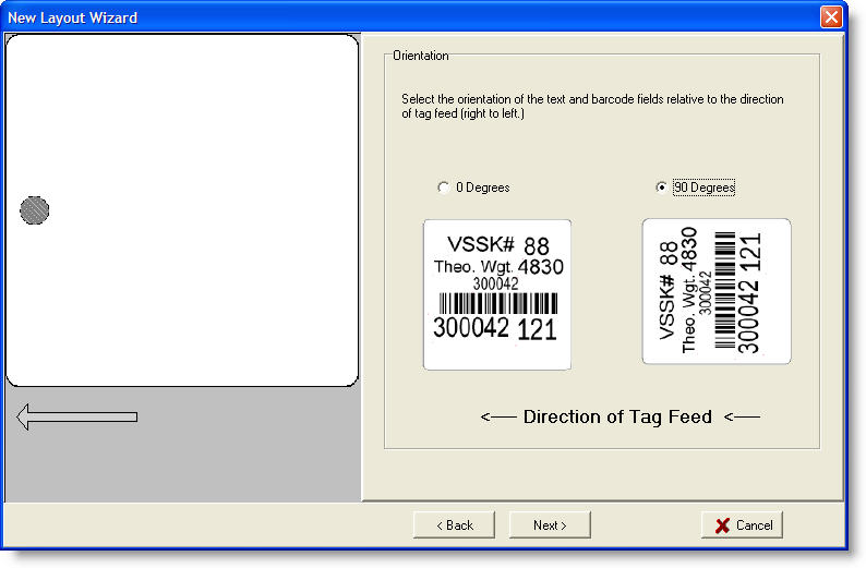
On this page, the wizard needs to know the orientation of the fields relative to the direction of tag feed. This direction is shown on the page as being from right to left. Select 0 degrees or 90 degrees as needed.
When you have specified the orientation of the fields, click the Next button to go to the next page of the wizard.
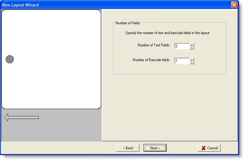
On this page, you must specify the number of text fields and barcode fields to place on your layout. Enter the number of each type of field and then click the Next button to continue.
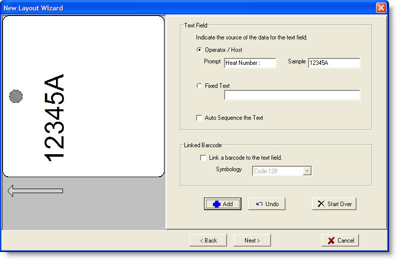
This page is where you add the individual fields to the layout. At the top is an area where you define a text field. You must specify the source of the data for the text field. You can choose the data source to be "Operator / Host" which means that the data will be typed in the the operator, or downloaded from the host. This corresponds to a "%V" flag in the field. If you select this source, you must also specify the operator prompt and a sample of the actual data that the field will hold.
If the data is to be the same each time, instead of selecting "Operator / Host", you may select "Fixed Text" and enter the actual text in the accompanying field.
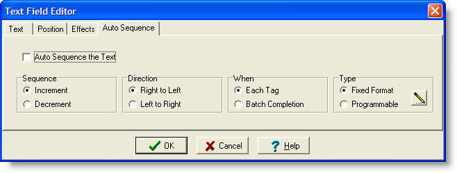
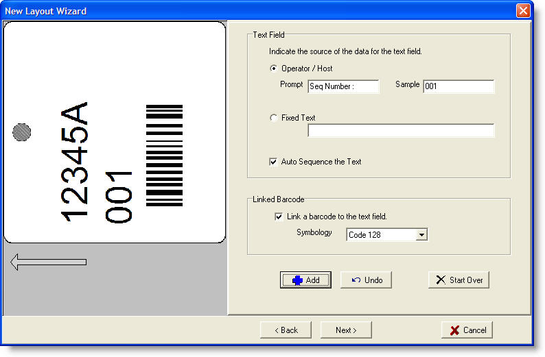
Regardless of the source of the data, you may indicate that this field is to be sequenced (serialized) on each print cycle. Check the "Auto Sequence the Text" box to enable sequencing.
Each text field may optionally be the source of data for a barcode field. By checking the "Link a barcode to the text field" box and specifying the barcode symbology, the wizard will automatically add a barcode for this text field.
Once you have specified the text field, and its optional linked barcode, click the Add button to have the field added to the layout. The layout image will be updated to reflect the new field. If you made a mistake, or wish to reverse the add operation, simply click the Undo button. If you wish to undo all of the fields you have added, click the Start Over button.
The wizard will select a size for your fields based on the number of text and barcode fields that you specified in the previous page. There is nothing to keep you from adding more fields than you previously specified, but they will not necessarily fit on the layout. If you want to add more fields, then it is recommended that you click Start Over, and then Back to change the number of fields.
Once you have specified all of the fields in your layout, click Next to continue.
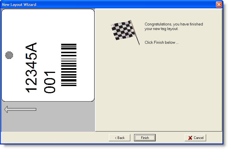
Congratulations, you have finished your new layout. If the layout is correct, click the Finish button. The new layout will be shown in the designer window where you will be able to modify it as needed for your application. Be sure to save the layout when you are finished.
Copyright © 2010 InfoSight Corporation All Rights Reserved
InfoSight ® is a registered trademark of InfoSight Corporation
 The
designer form contains a menu bar at the top. The menus provided are
File, Edit, View, Tools, Setup and Help. Each menu is
described in more detail below.
The
designer form contains a menu bar at the top. The menus provided are
File, Edit, View, Tools, Setup and Help. Each menu is
described in more detail below.
 The
file menu provides access to the program functions that deal with
loading tag layout files for editing, saving layout files, printing
reports, etc.
The
file menu provides access to the program functions that deal with
loading tag layout files for editing, saving layout files, printing
reports, etc.
 The
Edit menu gives you the ability to perform various editing operations on
the tag layout..
The
Edit menu gives you the ability to perform various editing operations on
the tag layout..
 The
align menu provides tools for aligning multiple fields in various
configurations.
The
align menu provides tools for aligning multiple fields in various
configurations.
 The
View menu allows you to control what you see on the designer form.
The
View menu allows you to control what you see on the designer form.
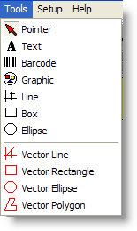 The
Tools menu provides access to the tools that add fields to the tag
layout. Each tool adds a different kind of field to the
layout. When you select a tool, it remains selected until it is
deselected by selecting the Pointer tool.
The
Tools menu provides access to the tools that add fields to the tag
layout. Each tool adds a different kind of field to the
layout. When you select a tool, it remains selected until it is
deselected by selecting the Pointer tool.
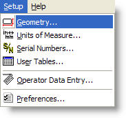 The
Setup menu
provides several features for configuring the composition and appearance
of the tag layout.
The
Setup menu
provides several features for configuring the composition and appearance
of the tag layout.
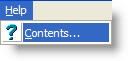 The
Help menu provides access to the program's built-in help facility.
The
Help menu provides access to the program's built-in help facility.