 |

LabeLase� Producer
|
|
LabeLase� Producer
|
|
The Setup menu is only available in the Supervisor mode of operation and provides several features for configuring the operation of the tag printer.
|
| Layout
This menu item will activate the Tag Layout Designer form, which allows the supervisor to create and/or edit tag layout files. You can also activate this form by double clicking the tag layout image.
|
| Printer Configuration
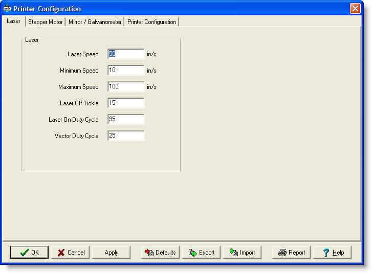
The Printer Configuration dialog allows you to enter the parameters that describe the configuration of the printer. Each model of LabeLase� printer has different characteristics and the software must be configured to match. The dialog has four tabs, each corresponding to a specific aspect of the printer's configuration: Laser, Stepper Motor, Mirror / Galvanometer, and Printer Configuration. Each of these is discussed in detail below.
Laser Speed - This field affects the �blackness� of the image produced by the tag printer�s laser by specifying the speed at which the laser is moved across the tag surface. The lower the setting for this field, the blacker the image will be. Note that print speed is affected by this setting: the lower the setting, the slower the print speed. Minimum Speed - New to Version 1.30. This field, along with the maximum speed (below), is used to set the range of the "Darkness" track bar on the main window. When the track bar is all the way to the right (darker), then this speed will be selected.
Maximum Speed - New to Version 1.30. This field, along with the minimum speed (above), is used to set the range of the "Darkness" track bar on the main window.
When the track bar is all the way to the left (lighter), then this speed will be selected.
Vector Duty Cycle - New in Version 1.80. This field specifies the amount of time the
laser is on when printing vector fields, expressed as a duty cycle (percentage.)
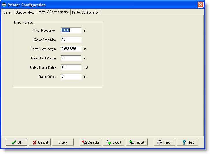
Galvo Start Margin - This field specifies the number of pixels in the margin at the start of each column of image data. Galvo End Margin - This field specifies the number of pixels in the margin at the end of each column of image data.
Galvo Home Delay - This field specifies the time, in
milliseconds, that the galvo must delay when returning to the home
position.
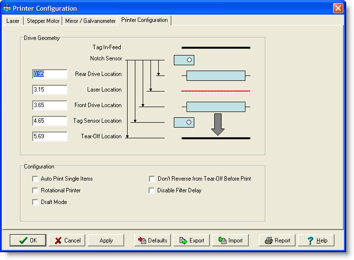
Rear Drive Location - This field specifies the distance from the notch sensor to the rear drive roller. Laser Location - This field specifies the distance in inches or millimeters from the notch sensor to the position where the laser burns the image. Front Drive Location - This field specifies the distance from the notch sensor to the front drive roller.
Tag Sense Location - This fields specifies the distance from
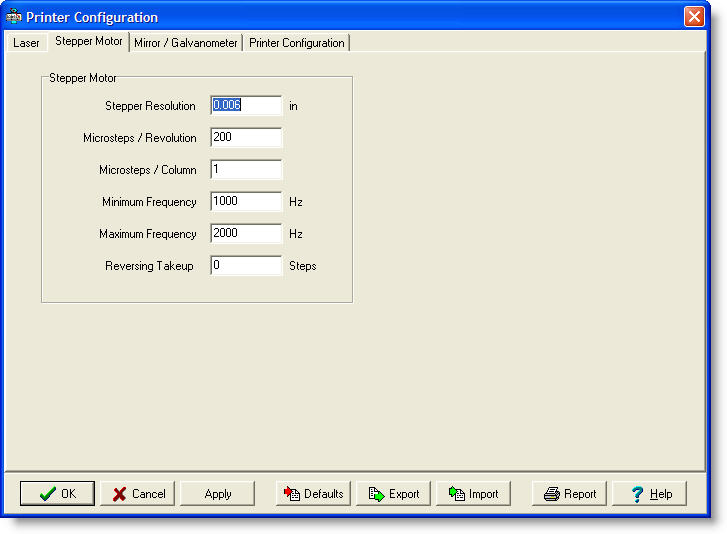
the notch sensor to the tag sensor. Draft Mode - This checkbox allows you to specify that you wish to run the printer in a lower resolution draft mode. When you check this box, the Stepper Resolution, Mirror Resolution, Microsteps / Column, Galvo Step Size and Laser Speed settings will be adjusted appropriately for you. Note that when in draft mode, barcode fields with odd scale settings will be distorted. Don't Reverse from Tear-Off Before Print - New in V1.70 - This checkbox will prevent the printer from reversing the tag material from the tear-off position before beginning the next print cycle. This setting is only useful in certain specialized printing applications and should normally be turned off.
Disable Filter Delay - New in V1.80 - This checkbox will disable the short delay used by the air filter when printing vector fields on special materials. Normally, the
air filter needs to be turned on several seconds prior to printing a layout containing vector fields. This allows air flow to be fully up-to-speed before printing
begins. However, in special circumstances, you may remove this delay. Contact the factory for instructions.
Export - New to Version 1.30, the Export button allows you to save the current settings as shown in this dialog to a file. You will be queried for the name of the file, which will have the extension .INI, and can be saved anywhere you choose. Once a file is saved, it can be recalled later using the Import button. Import - New to Version 1.30, the Import button allows you to recall the settings that were previously saved using the Export button. You will be queried for the folder and name of the file, which has a .INI extension. The Export / Import functions make it easy to save different printer configurations and recall them as needed. This may be useful for backup purposes, or if different types of tag stock are used frequently. |
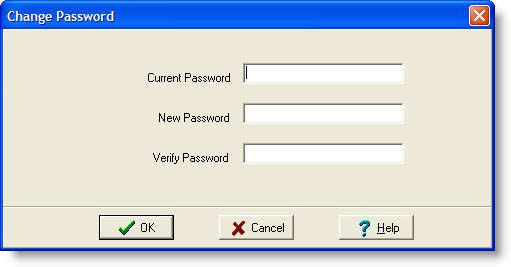
| Supervisor Password
To keep unauthorized personnel out of the configuration and maintenance functions of the program, you may set a supervisor password. This password is required to enter the supervisor mode of operation. |
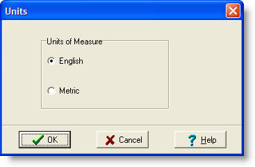
| Units of Measure
The program is capable of handling both English and Metric units of measure. You can set the units of measure as needed for your location. The unit setting effects the field locations in a layout, the printer configuration settings, user preferences, etc. |
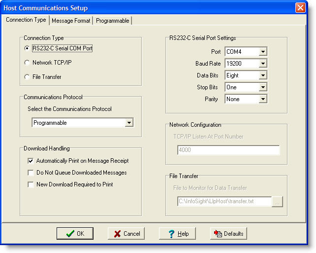
| Host Communications
Many tag-printing applications require that the data printed on the tags come from another computer called a host. The host computer must be connected to the tag printing computer via some type of communications medium and using some type of communications protocol. The LabeLase Printer software allows you to connect to another computer or network to facilitate the download of data to the printer.
File Transfer - When connecting to the host over a local area
network (LAN), it is possible to have the host computer supply data to
the printer by writing to a file on the printer's PC.
You must specify the full path to the desired file in the File Transfer
settings group box. The Producer program will monitor
for this file and when it appears, it will read its contents and queue
it for printing. After reading the file, it will be
deleted. Note that when File Transfer is the selected
connection type, the Protocol settings are disabled since no protocol is
required for this type.
Do Not Queue Downloaded Messages - This checkbox disables the queuing of data received from the host computer. When checked, only one message (the most recently received) will be �buffered� for printing.
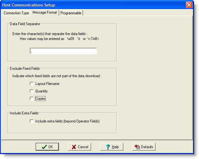
Beginning in Version 1.20, a new tab allows you to configure the message format. Note that the Data Field Separator entry was moved to this tab from the Connection Type tab. The Message Format tab is shown below:
Exclude Fixed Fields - The Standard Message Format begins with 3 fixed fields that specify the layout filename, quantity and copy count. In previous versions the fields could be omitted by simply having no value between the separator (e.g. ,,,) but the separator itself was required. In V1.20 and above, you can omit the fields altogether by checking the corresponding "exclude" checkbox in setup. Note that each fixed field is individually include/excluded. Include Extra Fields - In previous versions, the host could only write data into the corresponding Operator Entry fields of the layout. Any data sent from the host that did not have an associated operator entry would have been ignored. In V1.20 and above, the extra data can be placed directly into the text fields themselves. Each field after the last operator entry field is designated Field 1, Field 2 and so on. The layout text field with the same Link ID will be replaced with the associated data. For example, the data in the first field following the operator data will be placed into the layout text field that has a Link ID of 1.
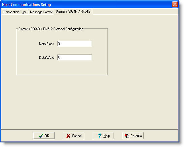
The Siemens 3964R / RK512 is a peer-to-peer protocol designed for communicating data and I/O information between programmable logic controllers (PLC) in the Siemens family. Using this protocol allows a Siemens PLC to send data to the Producer.
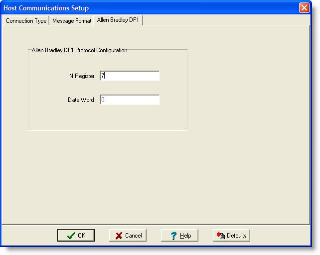
The Allen Bradley DF1 protocol is a peer-to-peer protocol designed for communicating data and I/O information between programmable logic controllers (PLC) in the Allen Bradley family. Using this protocol allows an Allen Bradley PLC to send data to the Producer. The DF1 protocol is the basis for the Allen Bradley Data Highway.
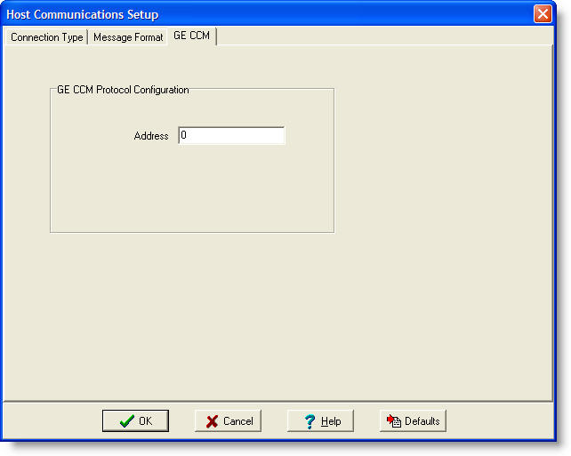
The General Electric CCM protocol is a peer-to-peer protocol designed for communicating data and I/O information between programmable logic controllers (PLC) in the GE family. Using this protocol allows a GE PLC to send data to the Producer.
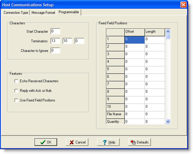
The Programmable protocol is not really a protocol as much as it is a mechanism to define a simple communications mechanism for data transfer between the Producer and another device that cannot or does not handle the other protocols available. Using the protocol�s settings, you can configure it to match a simple download of data from another device. |
| Preferences
There are certain settings that you can change to configure the program to your individual preferences. When accessed from the main Operator�s window, only the Startup preferences are accessible. When accessed from the Layout Editor, the Display and Format Toolbar preferences are accessible.
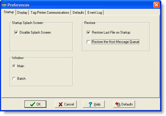
Startup - Startup preferences control the behavior of the program when it is started.
Restore Host Message Queue - When checked, the messages
downloaded from the host and waiting in the message queue will be saved
and restored between program invocations.
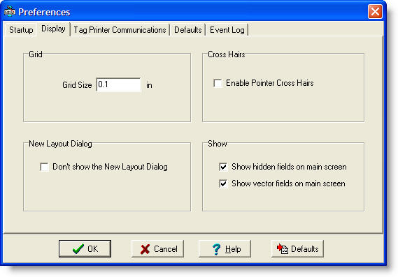
Grid Size - Enter the size of the grid as shown in the Layout Designer (in or mm). Enable Pointer Cross Hairs - When checked, the Layout Designer will show cross hairs that track the position of the mouse. This can be useful when adding or moving fields to ensure their proper position. Don't show the New Layout Dialog - When checked, you will not be shown the New Layout Dialog when creating a new layout. Show hidden fields on main screen - When checked, hidden fields will be shown on the tag image on the main screen. Show vector fields on main screen - When checked, vector cutting fields will be shown on the tag image on the main screen.
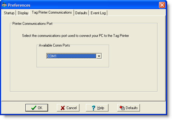
Tag Printer Communications - The tag printer communications preferences allow you to set the COM port to be used for communications to the tag printer. Important: The setting for the tag printer COM port must not conflict with the port chosen for Host communications.
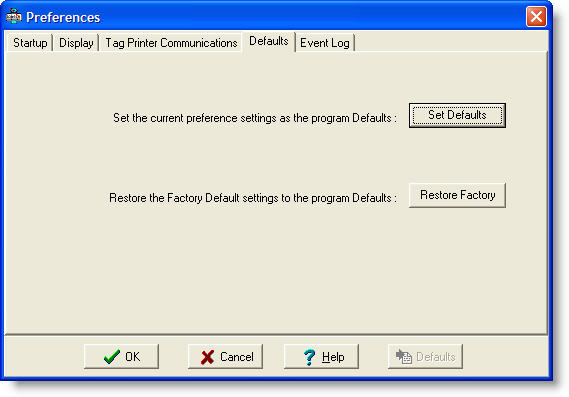
Defaults - The defaults tab allows you to set the current preference settings as the program's default values, or to restore the factory default settings as the program's defaults. Click the appropriate button as needed. Note that you will be required to confirm your intentions before the operation is completed.
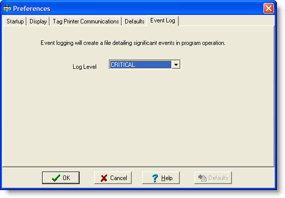
Event Log - The event log tab allows you to configure the level of event logging performed by the service version of Producer. Since the service has no user interface, it must record events and errors to a file for later inspection when resolving problems. The Log Level determines the severity of the events that get recorded, and can be set to CRITICAL, ERROR, WARNING, ADVISORY, STATUS and NOTICE. Setting the level to NOTICE will result in all events being recorded in the log file. It is recommended that under normal operating conditions that the level be set to CRITICAL so that only important errors are recorded. This will keep the size of the log file from growing too quickly. If you are encountering problems, you can temporarily lower the log level so that more information is recorded about the service's operation. Be sure to raise the level after the problem is resolved. The log file is located in the service program's folder, which is where Producer was originally installed.
|
Copyright © 2010 InfoSight Corporation All Rights Reserved
InfoSight ® is a registered trademark of InfoSight Corporation