LabeLase® Producer

Maintenance Menu


The Maintenance menu is only available when in the Supervisor mode of operation and provides several features that aid in the setup of the printer and diagnosis of any problems you may encounter. Note that under most circumstances, it will not be necessary to access these functions. If you must use these functions, do so only under the direct supervision of factory trained personnel.

Calibrate Laser

The Calibrate Laser dialog allows you to calibrate of the printer’s laser. This function is usually used by factory trained technicians only. The laser will burn a line across the tag and then step 50 steps forward.


Calibrate Motor

The Calibrate Motor dialog allows you to calibrate the printer’s stepper motor. Use this function to determine the stepper resolution. This procedure may be necessary after prolonged use of the printer due to wear of the drive roller. Follow the on-screen instructions to perform the Motor Calibration procedure.

When you click Next, the printer will burn a line across the tag material, step a fixed number of motor steps forward, and then burn another line across the material. Use a high precision measuring device such as a caliper to accurately measure the distance between these two lines.

Enter the measured distance into the "Distance between lines" field on the form and click Next. The stepper resolution will be computed and entered into the printer's configuration settings automatically.


Jog Motor

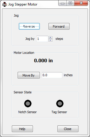
The Jog Stepper Motor dialog is useful for exercising the printer’s stepper motor. With this dialog, you can:

Jog the motor by single (or multiple) steps in either the forward or reverse directions.

Specify a specific position relative to the notch sensor and have the motor move there.

Monitor the state of the notch and tag sensors to determine if the sensors are functioning properly.

Reverse - This button will cause the motor to move in the reverse direction by the number of steps specified in the Jog By field.

Forward - This button will cause the motor to move in the forward direction by the number of steps specified in the Jog By field.

Jog By - This field allows you to specify the number of steps to move when jogging in either the reverse or forward direction.

Motor Location - This entry field display the current tag material position, which is the distance moved past the notch sensor. You may enter a new number here and press the Move By button, which will cause the motor to move to the indicated position.

Move By- This button is used in conjunction with the Motor Location to move the motor / tag material to a specific position relative to the notch sensor.

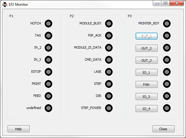
Notch Sensor - This is an indicator of the state of the notch sensor. When the notch is at the sensor, the indicator will glow yellow.

Tag Sensor - This is an indicator of the state of the tag sensor.
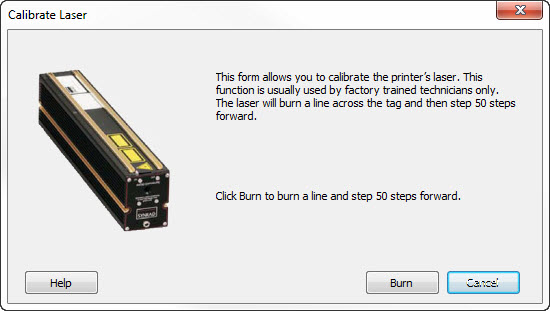
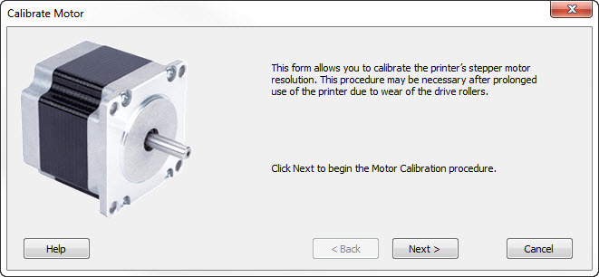
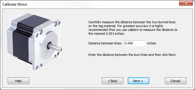
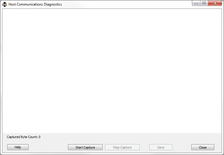
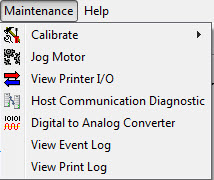
 

View Printer I/O

The I/O Monitor is a dialog that shows the status of the inputs and outputs of the printer. This screen is updated once each ½ second.

Inputs that are "off" are shown as dark, while "on" inputs are shown lighted in yellow.


Host Communication Diagnostic

The Host Communication Diagnostic is a helpful utility to diagnose problems with the download communication link between your host automation system and Producer.

Start Capture - Starts the capture of data coming from the host computer. Data will be displayed as it is received.

Stop Capture - Stop the data capture.

Save - Save the captured data to a file for archival or analysis using other tools.


Digital to Analog Converter

The Digital to Analog Converter Monitor is a dialog that allows a qualified technician to control the digital to analog converter in the printer. The DAC device is used to control the Galvo/Mirror movement.

DAC Channel - Select the desired channel for the DAC to be controlled. Note that not all printer models have more than one DAC channel.

Analog Voltage - Enter the desired analog output voltage or select it using the slider bar. Click the Set Voltage button to output the new value.

Oscillation - Calibration of the Galvo requires controlled waveform output from the DAC. Select the desired waveform type and click Oscillate to start. Click Stop to end oscillation.

Note: DAC maintenance should be performed by qualified personnel only.


View Event Log

View the log of events produced by the Producer or service programs as they execute. The event log is a text file and will be opened for viewing in the standard Windows Notepad application.


View Print Log

View the log of print jobs produced by the Producer or service programs as they execute. The print log is a text file and will be opened for viewing in the standard Windows Notepad application.


Copyright © 2021 InfoSight Corporation All Rights Reserved
InfoSight® is a registered trademark of InfoSight Corporation