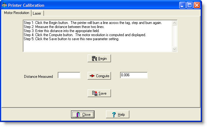
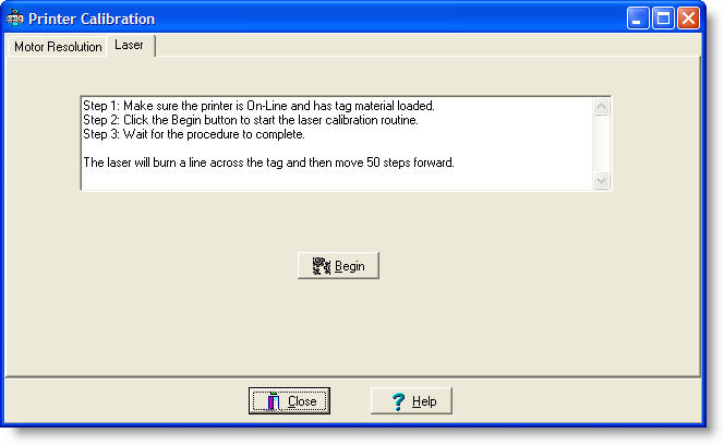
The Printer Calibration dialog allows you to perform two separate calibration operations.
The following adjustment and calibration procedures can be used to fine tune the tag printer�s operation.
- Calibrate Stepper Resolution
a. Feed at least 6 inches of tag stock into the rear in-feed slot of the printer.
b. Select �Maintenance � Calibrate�� from the LabeLase� Producer menu to go to the �Printer Calibration� form. Click on �Begin�. Two calibration lines will be burned on the tag stock.
c. Press the �Feed� button on the printer and feed the stock out of the printer until the two lines are visible. As accurately as possible, measure the distance between the lines and enter the decimal value in the �Distance Measured� field of the �Printer Calibration� form.
d. Click on �Compute� and then click �Save�. The stepper resolution should now be calibrated. The value should be about 0.00295 or 0.00296 inches or about 0.075 millimeters if using metric units.
e. Click on �Close� to return to the main form. Select �Printer � Unload Tags� from the menu (or reverse feed by pressing F8 until the tags are unloaded from the printer.)
- Adjust Tearoff Location
a. Feed a string of 3 or more tags into the rear in-feed slot of the printer. Press the �Feed� button twice to feed out 2 tags. If the tags do not align with the tearoff location, measure the amount of miss-alignment.
b. Go to the Printer Configuration form. If the tag feeds out too far from the printer, reduce the �Tearoff Location� setting by the amount you measured. If the tag did not feed far enough, increase the setting. Click on �Ok� to enter the setting and return to the main form.
c. Select �Printer � Unload Tags� from the menu (or reverse feed by pressing F8 until the tags are unloaded from the printer.) Repeat step a. Don�t forget to feed 2 tags before checking the alignment If necessary, repeat the adjustment until correct.
- Adjust Rear Drive Location (alignment of tag fed in from rear)
a. Unload the tags from the printer.
b. Feed in some tag stock into the rear in-feed slot of the printer.
c. Check the alignment of the first tag with the tearoff location. Measure any misalignment.
d. Go to the Printer Configuration form. If the tag feeds out too far from the printer, reduce the �Rear Drive Location� setting by the amount you measured. If the tag did not feed out far enough, increase the setting. Click on �Ok� to enter the setting and return to the main form.
e. Repeat the procedure until proper alignment of the first tag is achieved.
- Adjust Front Drive Location (alignment of the tag fed in from the front)
a. Unload the tags from the printer.
b. Go to the �Printer Configuration� form. Make sure that �Auto Print Single Items� is NOT checked.
c. Feed a tag into the front slot of the printer. Note the tag must be the same length as the tag loaded into the layout of the LabeLase� Producer program. Also note that the minimum length for single tags is 3 inches, so if you are using shorter tags, you will need to use a strip of 2 or more tags totaling 3 inches or greater.
d. Check the alignment of the tag with the tearoff location. Measure any misalignment.
e. Go to the Printer Configuration form. If the tag edge stuck out too far from the printer, increase the �Front Drive Location� setting by the amount you measured. If the tag fed too far into the printer, decrease the setting. Click on �Ok� to enter the setting and return to the main form.
f. Repeat the procedure until proper alignment of the tag is achieved.
- Adjust Laser Location and Galvo Offset (alignment of burned image relative to the tag)
a. For this adjustment, you will need to create a tag layout with a box at the outside edges of the tag. A box with a bold line (10) is recommended. The line edges should go clear to the edges of the tag layout.
b. Insert continuous tag stock into the rear of the printer. The tag stock should be of the same length tags as the layout created in step a. Make sure the stock is aligned correctly with the tearoff location. Print the tag with the box image.
c. Check the alignment of the printed box with the leading and trailing edges of the tag. If the box is printed too far forward (toward the front of the printer), the �Laser Location� setting (located in �Printer Configuration�) is too low. If the box is printed too far back (toward the rear of the printer), the setting is too high.
d. The top and bottom lines of the printed box may be used to check vertical alignment. The vertical alignment of the image is part of the internal calibration of the printer, however it may be �fine tuned� in the printer configuration by using the �Galvo Offset� setting. The units are in inches when using English units of measure, or in millimeters when using Metric units. �Galvo Offset� is normally set to 0, but a positive number will shift the image up and a negative number will shift the image down. Normally very small numbers (thousandths) will be entered here.
- Tag Sensor Location
a. This is provided for future use and should be set to the default of 4.8 inches.

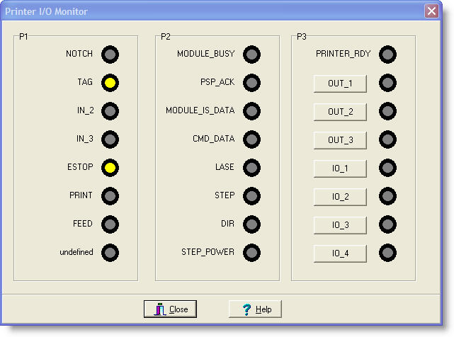
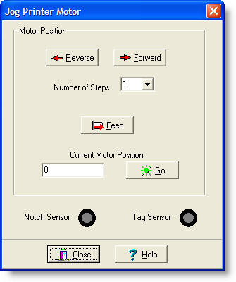 The Jog Printer Motor dialog is useful for exercising the printer�s stepper motor. With this dialog, you can: